 Hydraulic & Pneumatic Parts
ISC Companies is a distributor of mechanical power transmission parts. We can also supply certain parts used in fluid power applications/equipment. For more information about the brands we offer and/or pricing, please contact us by phone 763-559-0033, by email custserv@isccompanies.com, or by filling out our online contact form.
Fluid power involves two areas: hydraulics, when the working fluid is a liquid, and pneumatics, when the fluid is a gas. The basic principle of fluid power is that fluid under pressure produces an outward force on all surfaces in contact with the fluid. When fluid pressure acts on a movable surface, that force can be used to do work.
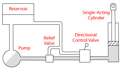
Basic Hydraulic System
Fluid power is typically the best way to produce high-force linear motion. Hydraulic motors have the advantages of torque limiting, compact size per horsepower, and ease of speed control. Electric motors are usually preferred for rotating applications rather than fluid motors and rotary fluid actuators.
Pneumatics is popular for industrial applications like stamping presses or automation robots, because systems are inexpensive, fast acting, safe, and clean. Both hydraulic and pneumatic equipment can handle shock and vibration, dust and dirt, heat and cold; they also require little maintenance and are often used in harsh conditions.
Hydraulic Fluids & Conductors
Fluids

The basic function of hydraulic fluid is to provide energy transmission, enabling work and motion. Fluids also lubricate components, transfer heat, and control contamination. Characteristics of an ideal fluid include: thermal and hydrolytic stability, low chemical corrosiveness, high anti-wear characteristics, low tendency to cavitate, long life, water rejection, constant viscosity, and low cost.
Common fluid types include: Petroleum-Based (the most widely used); Fire-Resistant/Water-Based (when petroleum-based present a hazard); Synthetic Oils (premium, high priced); Environmentally-Acceptable (used when spills can be damaging)
Conductors
Conductors (pipe, tubing, hose) are used to transport fluid from pumps to valves, actuators, and motors. Pipe and tubing are used where rigid lines are preferred. Pipe is commonly used in permanent applications with long straight runs with large amounts of fluid. Tubing bends easily and is used in applications where routing around obstacles is needed or when disassembly is frequent. A hose is widely used in applications where lines flex and bend. Reinforcement, construction, and dimensions vary among the designs, providing different pressure ratings and other performance features.
Connectors
Connectors fill the gap between the hose or pipe and the mating port on the pump, valve, or actuator. Common types include:
- Pipe Threads: Threads seal by metal-to-metal interference between fitting and housing. Pipe threads are widely used, inexpensive, and suitable for low pressure service.
- JIC 37 Degrees: Flare fittings that seal by conical, metal-to-metal contact between mating male and female seats. They are the most widely used connector in the US.
- Flat-Face O-Ring: A recessed O-ring seal is held in a groove on the male connector, which mates with a flat, finished surface on the female end when assembled.
- SAE Flange: Two styles: Code 61 and Code 62. Includes an elastomeric O-ring, set in a groove on the flange, that mates with the face of a pump, valve, or housing.
- SAE Straight-Thread: The port seals with an O-ring between threads and flange.
Filters
Filters are used because dirty fluids shorten equipment life, accelerate component wear, and lead to failure. Typically, a hydraulic system is cleaned by a single filter, usually in the return line. Ten micron is the most common filtration level. Many systems also have a suction filter on the inlet of the pump, which has a filtration system to remove large debris that could get into the reservoir.
 Hydraulic Pumps
A hydraulic pump, typically driven by an electric motor or internal-combustion engine, is the main power source of a hydraulic system. There are many different types of pumps that deliver less than one gallon per minute (gpm) to several hundreds of gallons. Pressures typically range from 500 to 6,500 psi. There are three basic designs: gear, vane, and piston.
- Gear-on-Gear: Consist of two gears that mesh inside a housing. As the gears rotate, liquid is drawn into the housing, compressed between gear teeth and housing, and delivered at pressure to the discharge port.
- Gear-within-Gear: Consist of an externally toothed gear that rotates inside and drives a larger internally toothed gear. As the teeth unmesh, a vacuum forms, drawing oil from the inlet. When the teeth engage, the oil is forced out of the discharge port. A common configuration is a gerotor pump.
- Vane: Consist of a circular rotor mounted eccentrically in a cavity. As the rotor spins, vanes extend and retract to seal against the cam ring. Fluid is trapped between vanes at the inlet, swept along by the vanes, and propelled through the outlet.
- Piston: The most efficient but higher cost. They convert rotary motion of an input shaft to a reciprocating motion of one or more pistons. Fluid is drawn into and forced out of a chamber by the piston, with valves controlling flow direction.
- Variable Displacement: Used in high power applications (over 15 HP) where flow varies over a wide range. When compared to fixed displacement pumps, they have lower power consumption, but are not as efficient and cost more.
- Fixed Displacement: Used when duty cycle is on-off, pump can be completely unloaded when not in use, and full flow from the pump is required under most operating conditions, even though load may vary.
- Pressure Compensated: Designed to hold the same pressure on the outlet during a back-stroke as during the power stroke.
Hydraulic/Pneumatic Valves
Valves are used on hydraulic pumps and air compressors to control fluid direction, pressure, and flow rate. Valve mechanisms are classified as a spool, poppet, slide, rotary, and diaphragm.
- Spool Mechanism: Used in pneumatic and hydraulic valves. They slide inside a sleeve, controlling flow between two ports. Characteristics: short stroke, low friction, little actuation force, and suitable for high pressures.
- Poppet Mechanism: A poppet covers an internal passage and is held in place by air pressure and a spring. When actuated, a stem pushes the poppet away from the seat to allow air flow. Typically used for heavy flows with minimum pressure drop.
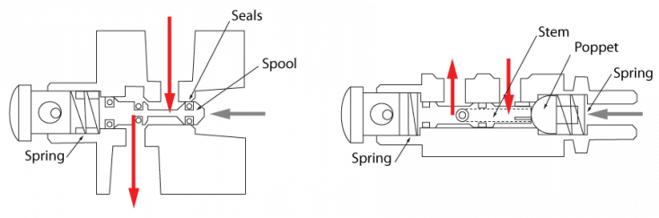
Spool (L) vs. Poppet (R) Mechanism
Pressure Control Valves
Pressure control valves modulate pressure level in fluid-power circuits. There are several types available and they are categorized by function.
- Relief: A spring holds the valve closed until the pressure level on the inlet port exceeds the spring pressure.
- Reducing: When the circuit reaches a predetermined pressure, the reducing valve restricts flow by moving the spool.
- Sequence: Normally closed. When pressure reaches preset levels, they permit flow between inlet and output ports.
- Unloading: When the pressure falls to a set amount, the valve closes and boosts pressure back to the preset level.
- Brake: Used for dynamic braking on a hydraulic motor. It has a relief valve where back pressure can be set.
- Counterbalance: Used to put a back pressure on the cylinder and prevent the load from uncontrollably falling.

Flow-Control Valves
Fluid flow is controlled by either throttling or diverting it. Throttling limits flow by reducing the size of an orifice and bypassing part of the flow around a circuit, so the actuator only receives the portion needed to perform a task. Types: Meter-In/Meter-Out Systems, Bleed-Off Systems, and Non-Compensated/Pressure-Compensated Flow Controls.
Directional Control Valves
These valves determine the fluid’s flow path through the circuit. They are classified by: Ports (number of plumbing connections to the valve); Position (number of stops the valve can make during operation); Way (possible flow paths through a valve).
Proportional and Servo Valves
Proportional valves are solenoid valves that vary the flow in proportion to the amount of current that flows though the solenoid coil. They are an inexpensive option for equipment requiring high-speed response at high-flow rates. Servo valves operate by using a remote electronic controller. Sensors mounted on actuators monitor position, speed, force, and acceleration. The actuator valve opens and closes based on these settings (closed-loop feedback).
Hydraulic Actuators
An actuator is a device for converting fluid energy into mechanical energy. Fluid-power actuators are available in many forms to provide specific types of actions. Generally all types of actuators are available for either pneumatic or hydraulic operation.
Cylinders
Cylinders are by far the most common type of actuator and work through linear extension. When fluid is pumped into a cylinder, the piston and rod are forced to move in or out against a load. Types include:
- Single-Acting: Simplest/lowest cost. Powers a stroke in only one direction.
- Spring-Return: A spring re-positions the piston to its starting point.
- Double-Acting: Most common, have two fluid chambers so pressure both extends and retracts the rod.
- Rodless: An internal piston is connected physically or by magnetic force to an external carriage.
- Servo Actuators: Transmit high forces while allowing computer control of rod velocity, acceleration, and positioning.

(L-R) Single-Acting Cylinders, Spring-Return Cylinders, Double-Acting Cylinders
Rotary Actuators
Rotary actuators turn an output shaft through a fixed arc. They produce high torque instantly in either direction, occupy little space, and are easy to mount. Two popular designs are rack-and-pinion and vane types. Rack-and-pinion uses fluid pressure to drive a piston connected to a gear rack, which rotates a pinion. Vane actuators consist of a shaft mounted in a cylindrical housing with one or more vanes attached to the shaft.

Rack-and-Pinion Rotary Actuator

Single-Vane Actuator
Hydraulic/Pneumatic Motors
Hydraulic and pneumatic motors are not as common as electric motors, but they are useful in specialized applications that have: high torque requirements, limited weight and space, subjection to stalling/holding loads, and the use of electricity is prohibited because of safety concerns. Type include:
- Axial Piston: Contain several pistons that are driven by high-pressure fluid.
- Radial Piston: Reciprocating pistons cause shaft rotation. Pistons are arranged in a circle with their bases connected to a plate that is mounted off-center to the output shaft.
- Gear-on-Gear: One of the most common for hydraulic units. Consist of a pair of matched spur or helical gears.
- Gear-within-Gear (Gerotors): Very compact for their displacement. An inner gear seals against an outer one to prevent fluid leakage. Tooth velocities and wear are low and power density is high.
- Vane: Consist of a slotted rotor mounted eccentrically within a circuit cam ring. As air or fluid enters, force is applied against the vane, turning the rotor and sweeping the fluid from inlet to outlet.
Pneumatic Compressors
A compressor moves specified volumes of gas against working pressure.They are similar in concept and hardware to hydraulic pumps. Because air is compressed, the water trapped in the air releases and gets in the pneumatic components. So, it is important to have a filter with water removal, a cooler to lower the temperature of the air after compression, and a dryer to remove as much water as possible. Types include:
- Vane: Inexpensive and require little starting torque
- Reciprocating: Pistons compress the air in the cylinders and valves that control inlet and outflow
- Diaphragm: The piston flexes a metal or elastomeric diaphragm compressing the air inside the cylinder
- Centrifugal: Operate at low pressures and are best suited to move large volumes of air
Hydrostatic Drives
Hydrostatic drives are often used where variable output speed is required. They offer fast response, maintain speed under different loads, and allow variable speed control from zero to maximum. A typical hydrostatic transmission (HST) has a variable-displacement pump and either a fixed or variable-displacement motor. Different configurations produce constant torque, constant power, or variable torque and power. Types include split and close-coupled (integrated transmissions).
 Content on this page was created using excerpts from the Power Transmission Handbook (5th Edition), which is written and sold by the Power Transmission Distributor’s Association (PTDA).
You must be logged in to post a comment.